Before putting the output stage PCB back into the subframe there are a few things to take care of. First is cleaning the frame, the heat sinks and the plastic spacers. To remove the glue on the frame I used paint remover followed by some alcohol cleaner and water with detergent. I looks almost as new again!


And after the cleaning...


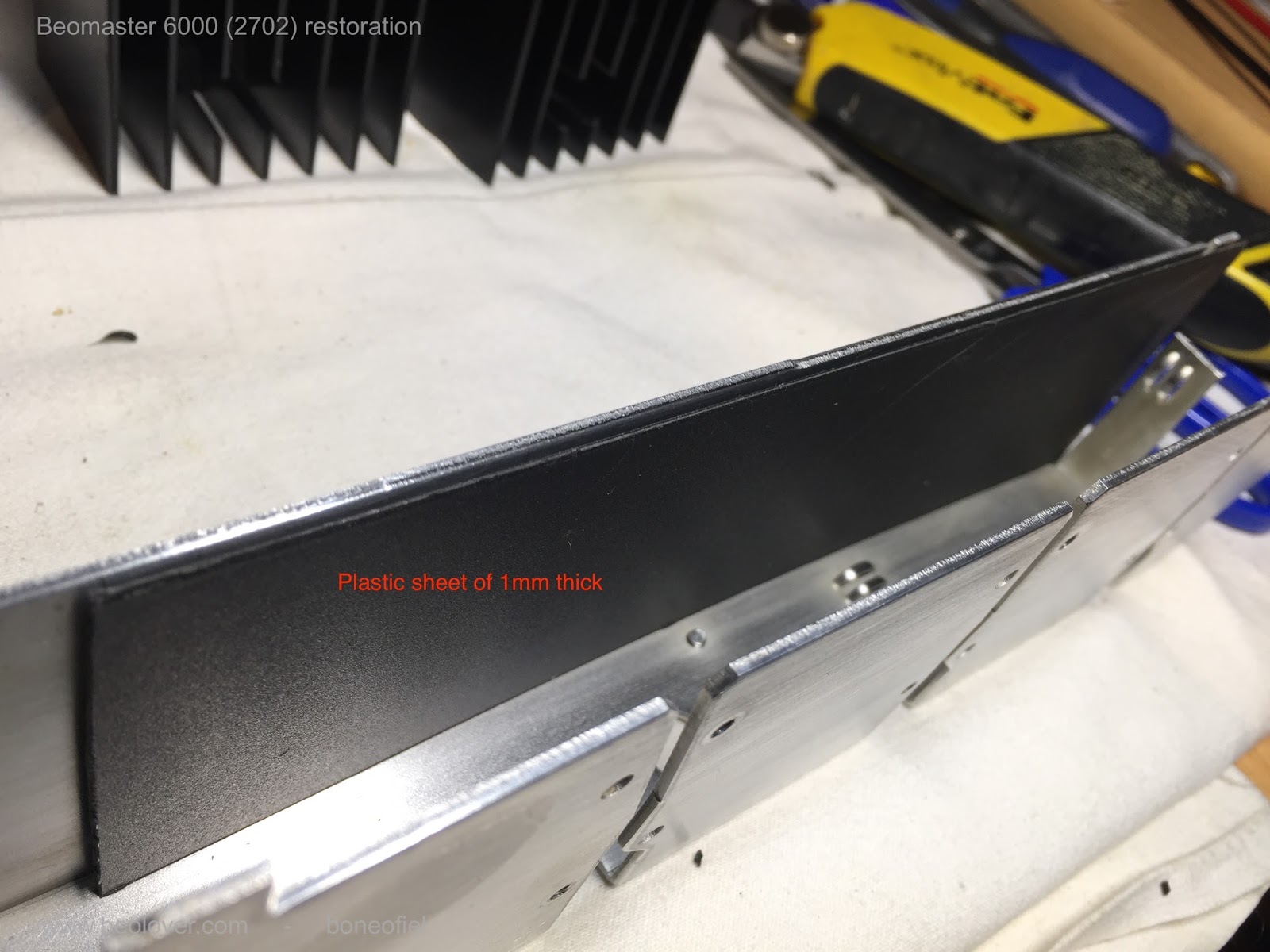
The warping of the output PCB has been mentioned a few times already and to avoid the common short circuits between the subframe and the solder side of the PCB I decided to use a permanent shielding in between. I used a sheet of 1mm thick plastic that I cut to size and glued on the inside of the subframe. Several cut-outs need to be done off course to fit everything back later and to give the wires, screws, etc. the space they need.


When I mounted the PCB I noticed something interesting: the warping of the PCB was almost completely gone. The reason is simple: the many wires that come from the 8 darlingtons transistors are longer than needed (to allow removal without desoldering) and are "stored" on the bottom of the subframe when everything is mounted. This cable tree however pushes against the board and makes it warp. There are tiny slots on the bottom of the frame (see picture above) that are supposed to hold the board in place. But they are to small and the board jumps out easily. As a precaution (probably not really needed) I glued a small plastic spacer on the board in order to keep the correct distance between board and frame. Again, probably not needed but it helps to get a perfectly aligned and straight board and that looks nice!


Up to the the heat sinks and the output darlington transistors. To make mounting easier and avoid breaking of, I replaced all the hard wires going the 8 darlingtons and the 4 transistors (that are also mounted on the heat sinks) with flexible wires. AWG 20 (0,5mm²) for the power darlingtons and AWG 24 (0,2mm²) for the other transistors. I tried to respect the original color code and was able to keep all but one original color. Note that the wires all have different lengths !

The mica isolators that are typically used are replaced with sil(icone)-pads. Some of the originals ones where cracked anyhow as you can see in the picture below. I know there is some debate about the pro's and con's of both. Some people stick to mica and use the needed thermal paste. Other swear to silpads. I'm in favour of the latter. It's easier and less messy since you don't need the white thermal paste anymore. I agree that one needs to be careful. These silpads can be punctured if something (like a tiny ball of solder) sticks between the transistor and frame (heat sink). Therefore it is wise to check the surface smoothness of the transistor (usually the collector connection) and the frame. Also, do not over-tighten the bolts or screws.


The plastic spacers are fixed to the subframe with a dot of glue, just enough to keep them in place.

The small driver transistors that are used for feedback of temperature and thus allow thermal stability of the power stage (the bias current) do need a bit of thermal paste since they are to small for silpads. One of them was fried on the right output channel and I replaced it with a authorised replacement (MPSA13).

Now all the heatsinks and transistors are mounted on the subframe.


Before moving on to the next phase, I checked a few things to make sure that there was no shortcircuit anywhere, that I had not mixed up the NPN & PNP darlingtons, etc. I found a fault in (again) the front right channel. Something was not measuring correctly. So I had to remove the board again and found a burned resistor 11R69 of 330 ohm that I had not noticed before. This resistor is in series with the trimmer that regulates the bias current. I did replace all the trimmers before but never checked them for burning out. I did now, and one off course was burned out. Normal, since the driver transistor O1C6 was short circuit on all tree connections!
 |
| should be "resistor" of course and not "transisitor" |
Checked again and so far so good. But no power yet applied to the board. That's for later.....
Rudy
ReplyDeleteThis is a major undertaking......as I'm familiar with the in's and out's of these machines I'm really enjoying following your progress, clearly the machine cannot have been fully functional when you received it
Major indeed! An exciting project!! I should point out that this project is done by Boneofil, and not by myself. It is a lot of fun to be a Beolover reader for once...;-)
Delete