Featured Post

Beolover SyncDrive: DC Platter Motor Replacement for Beogram 4002 and 4004 (Type 551x and 552x)

Late Beogram 4002 and the 4004 (Types 551x and 552x), which have DC platter motors instead of the earlier synchronous AC motors usually suff...

Monday, November 30, 2015

Beogram 4000: Installation of a New Gold Coated DIN5 Plug and a Grounding Switch

The beautification of the Beogram 4000 that I am restoring right now continues. I installed a grounding switch and a new gold plated Neutrik DIN5 plug. The grounding switch allows to combine signal and system grounds of the Beogram. This essentially allows to switch between the grounding scheme of the later 4004 models and the 4000/4002 set-up where system and signal ground are separated. Depending on the amplifier set-up it can be beneficial to be able to select either one to avoid the formation of ground loops that can cause humming. I recently made a post that illuminates this in more detail.

This shows the switch installed. The shown orientation corresponds to the original 4000 set-up with separated grounds. Flipping it to the left would connect both grounds:


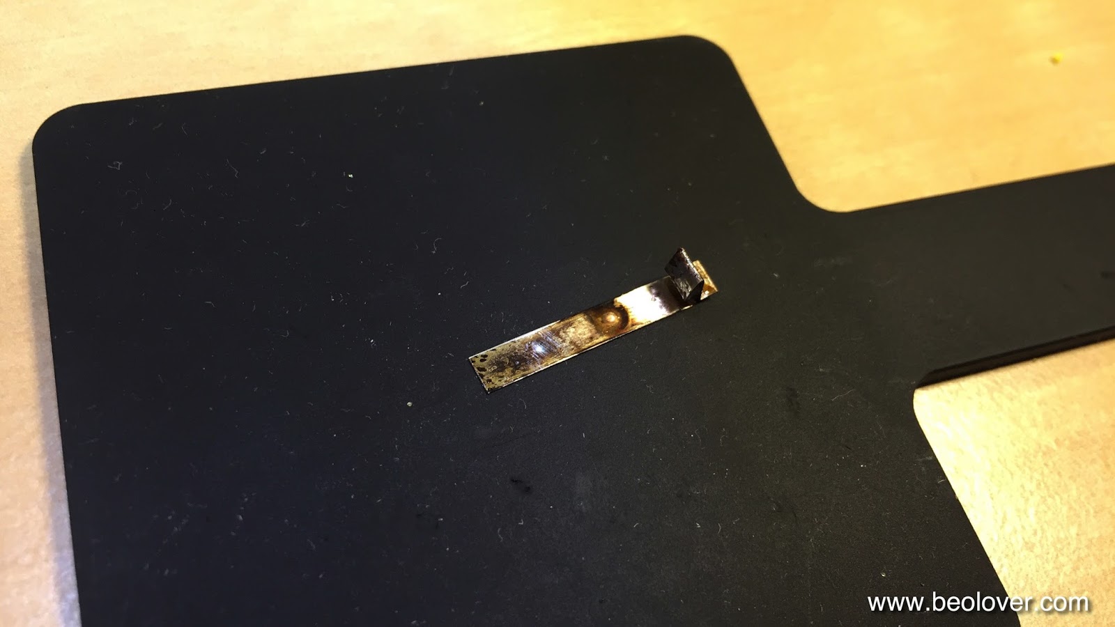
Here are a few pictures of the DIN5 replacement. This shows the corroded original plug:


And here is a picture of the new plug:

Beautiful! this shows the leads as connected on the inside:

Good to know that the precious MMC signals can now travel unimpeded!


Sunday, November 29, 2015

Beogram 4002 (5521): A New Arrival - First Impressions

A Beogram 4002 (5521) model in nice cosmetic condition arrived a couple of days ago for some TLC. The unit came with an indication of dead tracking sensor and 33 RPM light bulbs. It also came double boxed, which helped ensure uneventful travels (I recently made a video describing preparation for shipment and packing of a 4002/4. It is posted here). This shows the inner box:

and after taking the unit out: The foam pads held the sub platter down. Very important are the strips of no-residue tape holding the arms and the RPM panel in place during shipment.

The condition of this 4002 is very good except a few minor blemishes like a small shaved off bit of veneer on the right corner of the plinth:
The keypad is also in pretty good condition showing only minor finger marks on the coating:

The hood has the usual scratches commensurate with nearly 40 years of service:

Remarkable is that the Beogram 4002 lettering is missing on the aluminum trim in the back of the hood:

Finally there are a few marks on the arm weight cover, which hopefully can be removed:

Operationally, I noted that in addition to the dead light bulbs the motor urgently needs lubrication. It is emitting shrill noises when running without platter installed, a clear indication of dry sleeve bearings. Furthermore, the transport locks are disintegrating as is evident from the telltale orange plastic fragments distributed throughout the unit:

Unfortunately, the MMC20EN cartridge that came along has a suspension problem. The cantilever is at an off angle. It is interesting to note that the last 4002 that I restored also had an EN cartridge with exactly the same issue. I hope this is not a pattern...Here are a couple pictures:


This can be fixed by Schallplattennadeln.de or Soundsmith. Waiting for a reasonable offering on ebay is another option. In summary, however, I would say this 4002 is a pretty good starting point for a restoration.


Saturday, November 28, 2015

Vinyl Record Cleaner: Design Iteration 2

I cleaned a few records with my initial design of a vinyl record cleaner that uses Mr. Clean Magic Eraser pads. It seems to be very effective. Many previously crackly records sound now like new. Absolutely Magic!

But I was not satisfied with the handling of my initial design, and so I made a few changes. I beefed up the wall thickness by 0.5 mm and also introduced a longer pin that holds the record. That makes it much more straight forward to insert a record since one does not have to press it down anymore onto the lower pad to be able to get the pin through the center hole. Furthermore, a plateau was added at the outer end of the contraption that sits flush with the top part when both parts are put together. This took all instability and 'wiggle' out of it when pressed on a surface for the cleaning action. Here are a few pictures. The two parts with cut to size pads:

In action:

This shows the dirt that was taken out of the grooves of a 12" single of Foreigner's "Urgent" (one of my youth favorites...;-) that I recently bought via Discogs in "Near Mint" condition and that proved a big crackly disappointment:

Now it is running very quiet and could indeed be called 'Near Mint'. Mr. Clean rocks!


Beogram 4000: Adjusting the Chassis Springs and the Platter Height

The Beogram 4000 that I am rebuilding right now is entering the 'beautification phase'. It works now very well, and what is left are the exterior and a new good plated plug etc...So I set out to adjust the platter height and tilt and the leaf springs that hold the floating chassis of the turntable. This task is a relatively complex one since one has to "try[] to hit a bullet with a smaller bullet whilst wearing a blindfold, riding a horse" (to say it with Scotty in the 2009 Star Trek reboot...;-). Since sensor arm orientation relative to the floating chassis, platter tilt angle relative to the chassis, linear travel in the opened transport lock and belt tension all play significant roles in the adjustment process, one needs some patience and may have to redo things a few times until one hits the sweet spot where the platter is centered and leveled with the aluminum panels and parallel to the arms, and the chassis does not touch the locks when they are open.

I recently made a couple of videos that show the basic approach. They are posted here. Here are a few pictures of the fully adjusted platter relative to the aluminum panels:

And an 'in-action' detail. She is getting real pretty now!..;-): 

The aluminum panels were quite dirty on this unit. Here is an area in comparison before and after cleaning with Mr. Clean Magic Eraser pads and some (hand-) dishwashing detergent:
Before:

And after:

What would we do without Mr. Clean??!!


Thursday, November 26, 2015

Vinyl Record Cleaner

**************check out the latest version of the Vinyl Record Cleaner here******************

My vinyl collection keeps growing fast, and I often buy used records if there is no audiophile reissue available. Unfortunately, many vendors grade their vinyls only visually. This results in many disappointments even when buying 'Near Mint' or 'Mint' rated wares via eBay or Discogs et al... Often the records look pristine, but when played there is a lot of background noise and crackling due to dirt and dust lodged in the grooves. So recently I wondered about an effective way to clean such records, to restore them to an enjoyable quality. I poked a bit around and it seems the marketplace is swamped with overpriced record cleaning machines for hundreds and even thousands of $$...large amounts for a fairly trivial problem.

A while ago I realized that Mr. Clean 'Magic Eraser' is a powerful tool to restore the signature brushed aluminum surfaces on vintage Bang and Olufsen units. As long as there are no mechanical scratches one can usually restore the surfaces to a new-like appearance with these pads and some dish detergent (only use detergent for hand washing, not for machines since these detergents are aggressive and can possibly damage the surface of aluminum panels, but that is for another post...).

I started using the Magic Eraser pads on crackly vinyl a while ago and it seems to work pretty well. The fine foam of these pads very effectively conforms to small surface features, and it seems to be able to smoothly enter the grooves on records. The only issue I had with this method was that it was a bit cumbersome to consistently wipe the grooves with the pads in a circular fashion for a couple of minutes. So last night I sat there while listening to a crackly version of 'Softly as the Morning Sunrise' on the Modern Jazz Quartet's absolutely awesome 'Plays for Lovers'  (Prestige 7421) record and I wondered about a way for making this process more pleasant.

This is what I came up with: I printed the parts over night and in the morning I tried the design on the MJQ record. The design simply is made of two bars with 4" long cabinets for Magic Eraser strips and  a center pin to fit the record to be cleaned:

With pads inserted:

And here 'in-action' with the record inserted. I cleaned it for a minute with pads that I moistened with some detergent solution by just manually rotating the record, while pressing the top bar down to apply the pads. The design has a built in stop that one cannot touch the record with the plastic parts while pressing them together.

After the cleaning process I rinsed the record with tap water followed by filtered water from the fridge. Then I dried it with a soft cloth. After that the record was ready for a test spin. And strikingly, the crackling was mostly gone! Absolutely lovely! The whole process just took maybe 5 min. I now foresee some exponential growth for my record collection...;-).


Beogram 4000: Exchanging the Electrolytic Capacitors, the RPM Relay, and Adjusting the Motor Signal

I marched on with the restoration of the Beogram 4000 that is on my bench right now. After replacing the reservoir and motor capacitors, I went ahead and replaced all electrolytic caps on the main and power supply board with Japanese made 105C grade long lasting units. I also exchanged the RPM relay, since I recently extracted several dead or inconsistent relays of this type from Beogram 4000 and 4002 units. This made me think that these relays should be part of any 'full' restoration to ensure long-term stability. My goal is to get these elegant vintage beauties to a new-like performance and reliability. These pictures show the main PCB in its original state. This is the solder side. There is one Tantalum capacitor in the top left corner that was added post-PCB-design. Even the Danish masters go through a learning curve, I guess...;-):

Here is the component side:
And a detail shot of the RPM relay:

This is a picture of the relay component that I recently developed. It uses a modern encapsulated SMD relay that is broken out with a small PCB that fits precisely to the pinout of the original relay. Hence it can be plugged straight into the original solder pads and no external wiring is necessary. Plug'n Play!

This assembly is available to other enthusiasts. Just send me an email if you are interested.
This shows the PCB after replacing the capacitors and the relay:

This shows the replaced sole cap on the solder side:

On to the power supply board. It has only two Tantalum caps on it (the red dots):

And here with new ones:

After replacing the boards and testing that everything was working properly, I adjusted the motor signal. The AC motor is run by an on-board Wien bridge oscillator whose feedback needs to be adjusted for the right oscillation frequency for 33 and 45 RPM. There is also a potentiometer that controls the amplitude that goes into the power amplifier that finally drives the motor. I recently made  some more detailed posts (link 1, link 2) about the adjustment procedure. Here is a picture that shows how to apply the probes for the measurement:

One needs to be careful to select the right end of the phase capacitor to get the correct amplitude as prescribed in the manual for 33 RPM (6V). Here are the oscilloscope shots after I adjusted the trimmers to spec. This is the 33 RPM trace

and here is the one for 45 (it will usually be a bit lower than 6V and there is no way to independently adjust it - this is analog technology!..;-):

Beautifully clean traces in this unit! Absolutely lovely! This is Beolove!


Wednesday, November 25, 2015

Beomaster 6000 (2253): Volume Belt Installed Four Years Ago All Cracked Up

I am selling a Beomaster 6000 (2253) that I fixed up in 2011. Back then the off-ebay unit had lost its volume belt and so I ordered a new one. Well, I ran it the last two weeks and it worked fine. Then I decided to open it up and have a look, just 'to make sure' before sending it off. And what I found was this:

The belt was all cracked up and only barely still kept it together. A few more months and it would have died for sure. The way this belt looked it is a clear sign that I was sold a BUNA N O-ring seal back then instead of a EPDM transmission belt with round cross-section (I learned about BUNA N the hard way when I did the motor unit of my Beomaster 6000 4-Channel for the second time). I went to my trusted source, the "O-Ring Store" and ordered a bunch of EPDM rings. The BUNA ring measured 1-3/4" diameter, but EPDM is softer. I tried a few sizes and in the end I settled on the 1-1/2 diameter E70029 type which ran without slippage and gave me a taut feeling. Here is an impression:
Beautiful! This should last a while. BTW: The belt is easy to replace. One can simply pull off the string pulley from the volume potentiometer, place the ring over it and stick it back on the shaft. Carefully done, this avoids having to mess with the string driven volume indicator.


MMC20 Cartridge Mount Replacement: Gold Plating of Contacts

I had some fun last night with learning how to coat the contacts of my MMC20 mount reproduction part with gold. This is a follow up to this post. I think naked copper traces are not good enough for long term stability on this part due to oxidation issues. I used an electroplating solution soaked wand and 4.5V DC with the negative lead connected to the traces to be coated (metal ions are positive) and the positive to the wand. After a few minutes working the wand I saw a golden sheen on the copper...this picture shows the coated traces in comparison with some uncoated ones:

After this success I studied up a bit more about gold plating and it seems that the microelectronics industry standard is to put a nickel diffusion barrier between the gold and the copper...I guess I need to get some Ni electrolyte going. I also need to test for adhesion, there are some interesting test procedures for meeting the electronics industry standards. But I guess I am one step closer to the final design!

Monday, November 23, 2015

Beogram 4000: Installation of New Reservoir and Motor Phase Capacitors Using a 3D Printed Adapter

It was time to replace the big capacitors in the Beogram 4000 that I am rebuilding right now. I always enjoy this procedure, especially due to the clean install enabled by my 3D printed adapter. It accommodates smaller modern capacitor units, while giving the entire set-up an organized look. I made an earlier post that shows in detail what leads are connected where, in case you get confused while doing this procedure...there are a quite a few jumpers to re-solder...;-).

Here is a picture of my capacitor kit with adapter (this is available to other enthusiasts - just send me an email). The two back-to-back caps on the left replace the original bipolar AC motor phase capacitor. The adapter has notches that fit to the original capacitor mounting strap holding everything firmly in place:

I used this kit to replace this fairly messy original set-up:

This is how it looks now after installation:

And here a detail picture of the connections:

On to recapping the PCBs and adjusting the motor trimmers.


MMC20 Cartridge Mount Replacement: Third Design Iteration

This is a follow-up to my initial posts about the design of a MMC20 cartridge mount replacement. The first design iteration is discussed here and the second one here. The result of the second iteration was pretty close as in that I was able to stick a cartridge on it and that the base fit into the arm tube of a Beogram 400x. The issues with V2 were that the angle at which the cartridge mounted was about 4 degree off and that the cartridge was a bit loose. Furthermore, the nylon based print was too flexible. 

Version 3 shown here uses a different, stiffer material and I changed the geometry a bit to ensure proper mounting angle and a tighter cartridge fit. Here are a few impressions:

The mount now fits with a decent press fit into the arm tube (I did have to sand it slightly - a concession to the still imperfect printing tolerances at Shapeways). It also looks fairly original, although the material is a bit rough in difference to the original injection molded plastic:

The good thing is that the tab is invisible once the cartridge is mounted. Here is a picture of the fit:

Quite prefect now, I would say...After I stuck the cartridge on I measured the coil resistances while wiggling the mount a bit. It seems the contacts between mount and cartridge are now stable!
To get this ready for prime time, however, I still need to learn to gold-plate the Cu strips. Another point is to find a more perfect way for glueing the contacts PCB. Beolove springs from continuous improvement! But I am fairly positive now that this design is getting pretty close for some in-situ testing.


Saturday, November 21, 2015

Beogram 4000: Cleaning the Switches

One of the main trouble areas of the Beogram 4000 design are the many mechanical unencapsulated switches throughout the units. In my experience, most usability issues have their root-cause in one or more switches that are oxidized or have bent contact tabs. Often, when issues arise people try to fix them by bending the contact tabs and that usually results in even worse performance. The Beogram that I am restoring right now was no exception. When I tested its functions after replacing the alien solenoid I found that the slide transfer button to the right did not work.
So when I replaced the light bulbs in the control panel with SMD LEDs I also cleaned the contacts of the switches. The make-switches (DOWN/ON/OFF/33/45) can be restored by simply sliding some 2000 grit sand paper through the contact areas while pressing the switches and then adding some DeoxIT D-100 to the area. However the slide transfer buttons to the left ("<") and the right (">") are both break- (slow scanning) and make-(fast scanning) switches, while the UP-button is a break switch. Since break switches make their contact solely via the spring forces of the switches they need to be cleaned more thoroughly. It turns out that these switches are best extracted and then cleaned with a fiber glass pen followed by a thin DeoxIT coat. After that treatment they usually start working again.
This shows the left scanning switch taken out. It was very oxidized

This shows it after cleaning it with a fiber glass pen and re-installing it:

Her is the right one:

And after installation:

And finally the UP switch before

and after cleaning:

After this was done the scanning function was restored. Then I did the position switches that trigger needle drop at the standard vinyl diameters and also govern start and stop behavior. These switches are below the carriage assembly, i.e. one needs to take out the position indicator (careful with this since it is easy to break off the red indicator - this Beogram already suffered this indignity at some point as is indicated by the glued indicator). This shows the switches as I found them. They were covered with a lot of grey grease:

I cleaned everything,

and then I removed the two screws that hold the PCB in place after which I was able to lift it up:

The 2000 grit treatment followed by some DeoxIT D-100 did the trick. Now the control system works again smoothly.